1
General Information
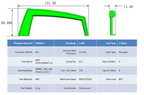
General information is an overview of the data of your part design and the coming mold. It helps you and the mold maker to double-check all the data before proceeding.
Part Data
Part dimension, part weight, part material — all the essential specifications of your design are verified and documented.
Mold Data
Mold steel, feed system, gate type — key mold construction parameters are outlined for your review and approval.
2
Mold Layout & Size
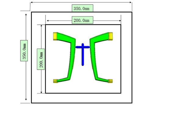
Mold Layout shows how the runners will be laid out. If you have a tooling engineer, they can double-check if the layout is right for your mold.
The mold layout determines cavity arrangement, runner system design, and overall mold dimensions — critical for both cost and quality.
Learn more about runners →
3
Gate
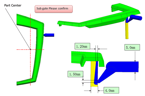
The gate in the report is not your only option. You can let us know if it affects cosmetics or functionality. Our engineers will recommend the optimal gate type based on your part geometry and requirements.
Sub Gate
Automatically trimmed during ejection. Ideal for parts requiring no visible gate marks on the appearance surface.
Edge Gate
Located on the parting line. Simple and cost-effective, suitable for most general-purpose applications.
Find out other types of gate →
4
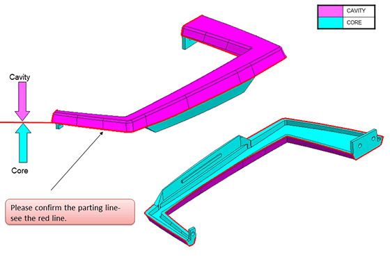
Parting Line
Most parting lines are usually located on the edges of the molded parts, which looks like "invisible". However, some lines may be obvious, which locate in or around the middle of the part.
Parting line placement is one of the most critical decisions in mold design. It affects both the appearance and functionality of the final part.
Learn more about parting lines →
5
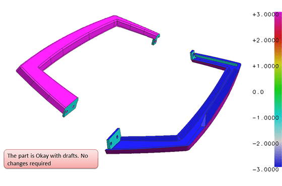
Draft Analysis
You can send us your design with draft added, or we can do this job for you. Thanks to advanced software, we can analyze what drafts are necessary very fast.
Recommended Draft
A minimum of 1° per side is recommended for most applications. Textured surfaces may require 3-5° depending on texture depth.
Insufficient Draft
Without adequate draft, parts may stick in the mold, causing scuff marks, part deformation, or even mold damage during ejection.
Learn more about draft →
6
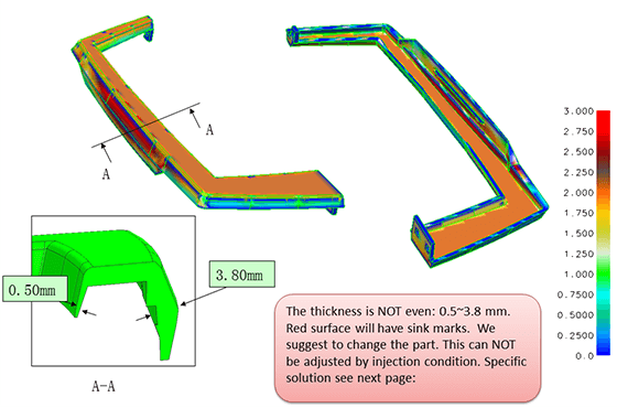
Thickness Analysis
We do thickness analysis for your part. If the wall thickness is not uniform, you will have to re-design the part to eliminate the issue of sink marks, or you can accept the issue if sink marks do not affect cosmetics.
Uniform Wall
Uniform wall thickness ensures even cooling, reduces warpage, and produces cosmetically acceptable parts consistently.
Non-uniform Wall
Thick sections cool slower, causing sink marks, internal voids, and dimensional instability in the finished part.
Find out wall thickness for specific plastics →
7
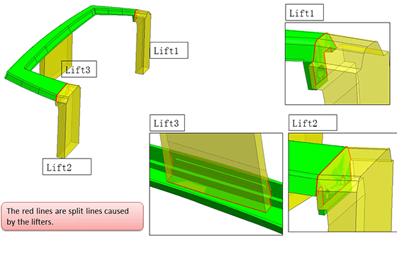
Lifters or Slides
Lifters or Slides are areas of the plastic injection molds that are used for creating undercuts. There are split lines left after movement of lifters or slides.
If split lines from lifters or slides are not acceptable for your part's appearance, you will need to re-design the part to remove undercuts entirely.
Lifters
Internal lifter mechanisms create undercuts on the inside of parts. They leave witness marks on the interior surface.
Slides
External slide mechanisms create undercuts on the outside of parts. Split lines are visible on the exterior surface.
See solutions here →
8
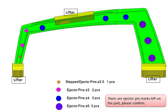
Ejector Pin Marks
Marks left by ejector pins, which are long pins used in the injection molds to push the final molded product out of the mold. The marks cannot be removed due to the process of injection molding.
While ejector pin marks are unavoidable, their location and size can be optimized. We'll recommend pin placement on non-cosmetic surfaces whenever possible.
Learn how ejector pins work →
9
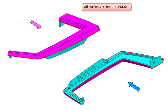
Surface Finish
Surface of texture or polish should be decided before machining the molds. It is not recommended to change them after the mold is created, which might be too late, as the draft may not be machined again as specified texture.
VDI Texture
VDI 3400 standard textures ranging from fine to coarse. Common in industrial and consumer product applications.
SPI Polish
SPI A1~D3 finish standards from mirror polish to rough texture. Selection depends on cosmetic and functional requirements.
Learn more about texture →