B
Bosses
Bosses are cylindrical projections on a plastic part, typically used for fastening, alignment, or as mounting points. They often have holes for screws or other fasteners and are reinforced with ribs to prevent cracking during assembly.
C
Cavity
The cavity is the concave portion of the mold that forms the outer surface of the molded part. It is one half of the mold, paired with the core, and together they define the complete shape of the part.
Cavity Number
Cavity number refers to the number of identical parts produced in a single molding cycle. A single-cavity mold produces one part per cycle, while a multi-cavity mold produces multiple parts simultaneously, increasing production efficiency.
Cold Runner
A cold runner system channels molten plastic from the injection nozzle to the mold cavities without heating. The runner material cools and solidifies with the part, and must be separated and either recycled or discarded after ejection.
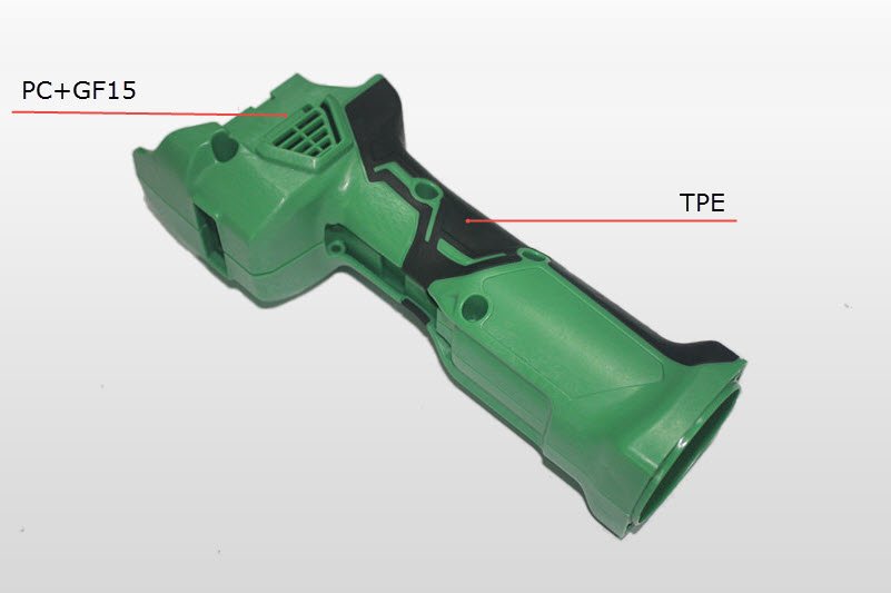
Co-Molding
Also known as: Two-shot molding
Co-molding is one form of overmolding. It refers to two plastic materials bonding together, which usually are a hard material like ABS and a soft material like TPE. Co-molding provides aesthetically pleasing color contrasts and ergonomic benefits.
Learn more →
Core
The core is the convex portion of the mold that forms the internal surface of the part. It is the opposite half of the cavity and together they create the full three-dimensional shape of the molded part.
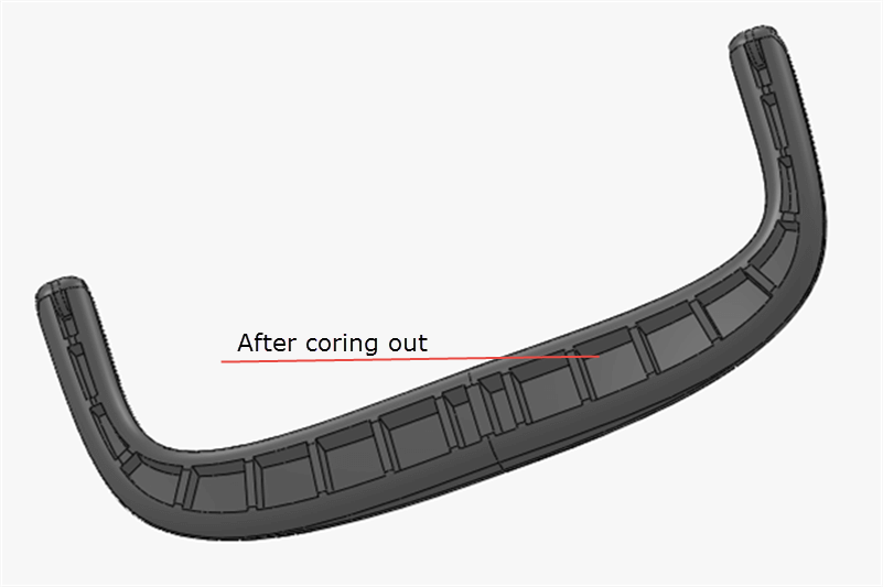
Core Out
Core out refers to a technique where you remove material from a plastic part, leaving distinct walls and ribs which provide enough strength and mating surfaces for other parts in the assembly. This helps reduce material usage, cycle time, and sink marks.
Learn more →
D
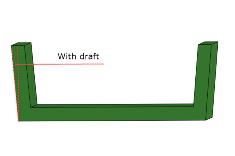
Draft
Also known as: Draft angles
Refers to the portion of an injection molded part that has some taper to make it easier to remove from the mold. Generally, all plastic components should be designed with draft where possible. A minimum of 0.5° to 1° per side is recommended.
Learn more →
E
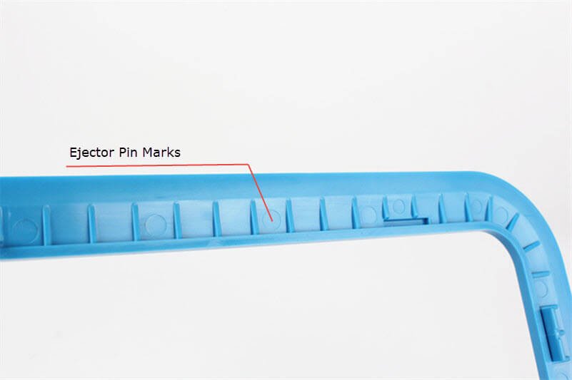
Ejector Pin Marks
Marks left by ejector pins. Ejector pins are long pins used in injection molds to push the final molded product out of the mold. The marks cannot be removed due to the process of injection molding, but can be minimized with proper design.
Learn more →
F
Family Mold
A family mold is a mold that contains multiple cavities producing different parts in the same molding cycle. This is cost-effective for small sets of parts that are always used together, though it can lead to imbalanced filling and varying quality.
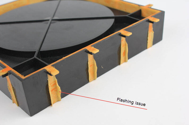
Flashing
Also known as: Flash
Flashing refers to plastic that leaks into a fine gap in the parting lines of the mold to create an undesired thin layer. It is a common defect caused by worn molds, excessive injection pressure, or poor mold alignment.
Learn more →
G
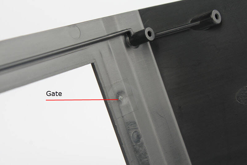
Gate
Also known as: Gate location
The gate refers to where the plastic enters into the cavity of the mold. It plays the role of the link between the part and the runner system. Gate type and location significantly affect part quality, appearance, and structural integrity.
Learn more →
H
Hot Runner
A hot runner system uses heated channels to keep plastic in a molten state as it flows from the injection nozzle to the mold cavities. Unlike cold runners, hot runners eliminate waste material and reduce cycle time, but add complexity and cost to the mold.
I
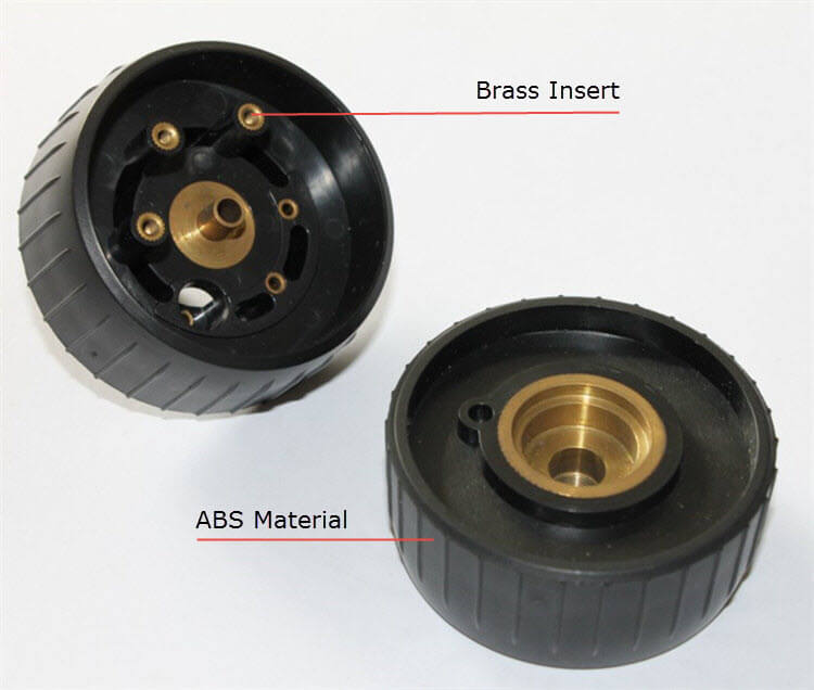
Insert Molding
Insert molding involves molding plastic around a core or "insert." Most often, the insert is a metal object, such as a pin, blade, threaded rod, electrical contact, wire, and others. This creates a strong bond between the insert and the plastic part.
Learn more →
O
Overmolding
Overmolding is a two-step injection molding process where a second material is molded over a previously molded part. This creates multi-material products with enhanced grip, sealing, or visual appeal. Common combinations include rigid plastic substrates with soft TPE or rubber overlays.
P
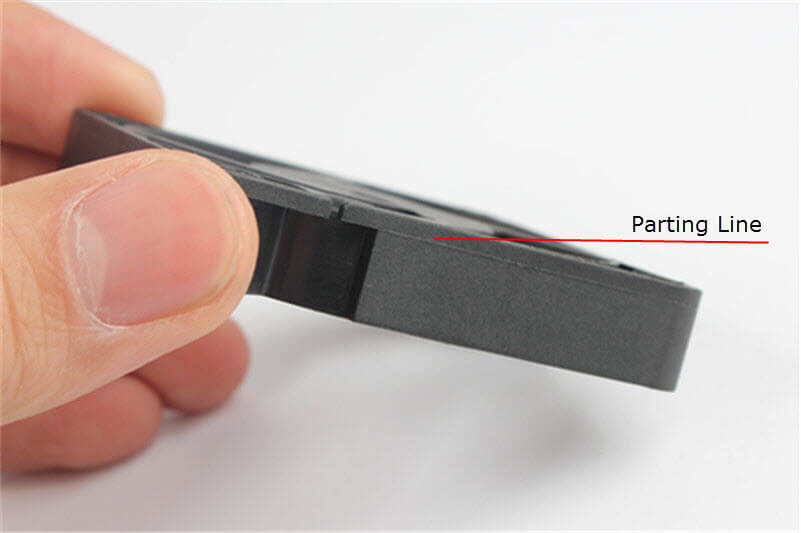
Parting Line
A parting line is the "line" or "seam" of separation on the part where the two halves of the mold meet. It cannot be avoided but can be strategically placed to minimize its visual impact. Proper design considers parting line location for both aesthetics and mold functionality.
Learn more →
R
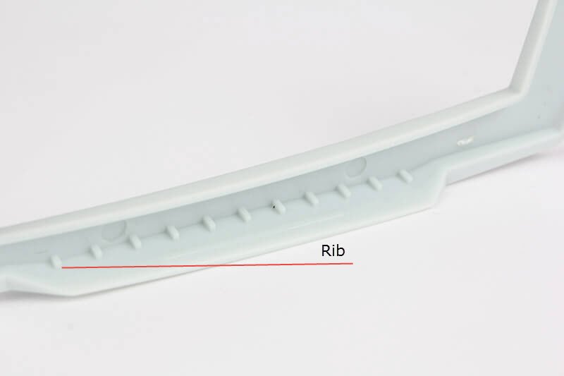
Ribs
Ribs refer to thin bladed features on a part that are used for strengthening wall sections and bosses. Ribs help eliminate sink marks and minimize warpage by providing structural support without increasing wall thickness. Recommended rib thickness is 50-60% of the nominal wall.
Learn more →
Runner
The runner is the channel that connects the sprue to the gate, allowing molten plastic to flow from the injection unit into the mold cavities. Runner design affects filling pattern, pressure distribution, and material waste.
S
Slide
A slide is a mold mechanism that moves laterally to form undercuts or side features on a part. When the mold opens, the slide retracts to release the part. Slides add complexity and cost to mold tooling but are necessary for parts with side holes, notches, or threads.
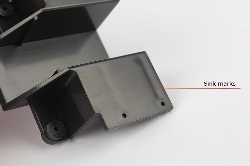
Sink Marks
Also known as: Shrink marks
Sink marks refer to areas of the molded part where it seems to be sunk in. They typically occur opposite thick sections, ribs, or bosses where the material shrinks more during cooling. Proper rib design and wall thickness control can minimize sink marks.
Learn more →
T
Texture
Texture refers to the surface pattern or finish applied to a mold cavity, which is then transferred to the molded part. Textures can range from fine matte finishes to deep grain patterns, and are specified using standards such as VDI 3400, SPI, and Mold-Tech (MT).
Thin Steel
Thin steel refers to areas in a mold where the steel between two features is very narrow. Thin steel areas are prone to breakage during molding and require special attention in design. Minimum steel safe distances should be maintained to ensure mold durability.
U
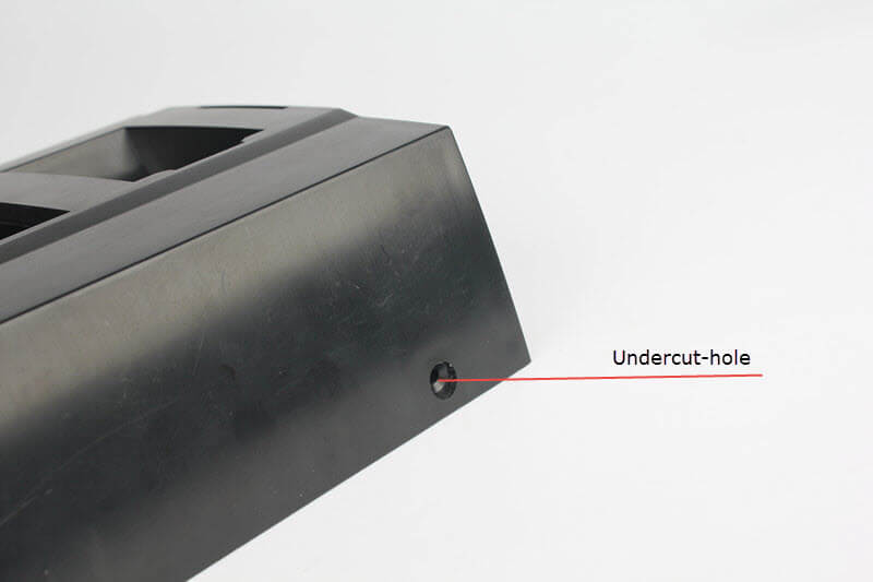
Undercuts
An undercut is any indentation or protrusion that prohibits ejection of a part from a one-piece mold. Undercuts add cost to tooling and molding, and are recommended to be eliminated or minimized whenever possible. When unavoidable, side-action cores or lifters are used.
Learn more →
W
Wall Thickness
Wall thickness refers to the distance between the outer and inner surfaces of a plastic part. Uniform wall thickness is critical for preventing defects like sink marks, warpage, and voids. Recommended thickness varies by material, typically 1.5-3mm for common engineering plastics.
Warpage
Also known as: Bending, Warp
Warp is the area of an injection molded part that distorts or bends during cooling or molding. It is caused by uneven shrinkage due to non-uniform wall thickness, improper cooling, or material orientation during filling.
Learn more →
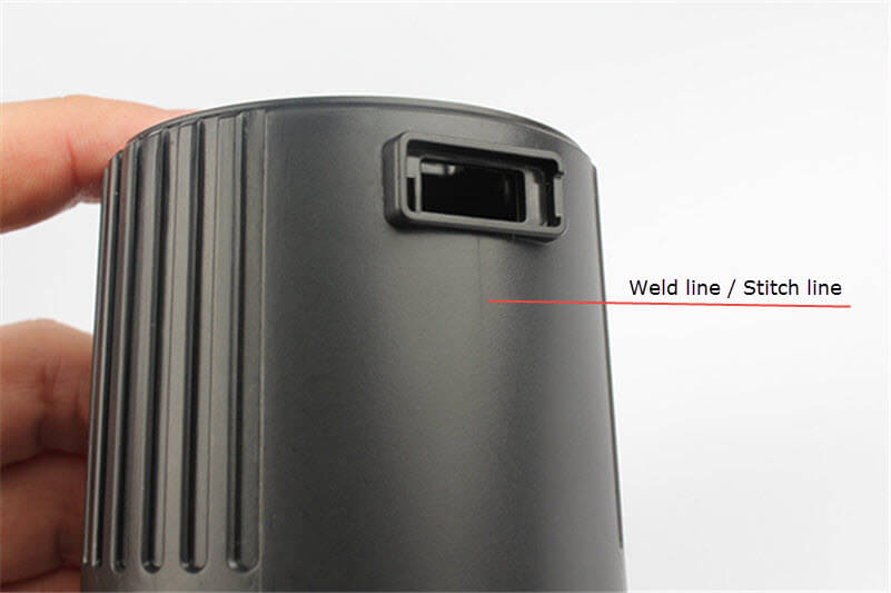
Weld Lines
Also known as: Stitch lines, Knit lines
Weld lines are imperfections in the part where separated flows of cooling material meet and rejoin, often resulting in a visible line. They occur around obstructions like cores or inserts and can weaken the part structurally if not properly managed.
Learn more →