
Common Injection Molding Defects: Causes, Fixes, and How We Prevent Them
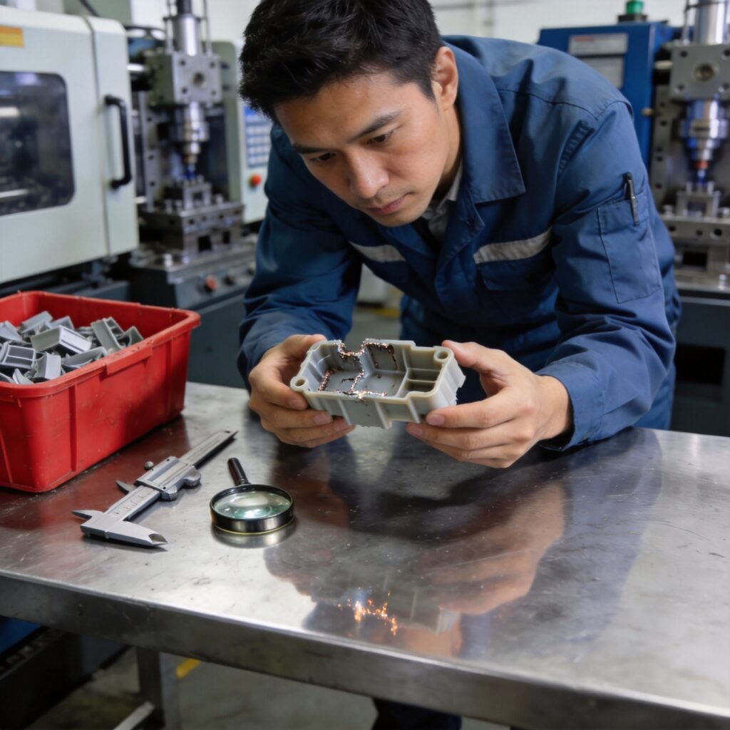
Every injection molding project hits defects at some point. What separates a reliable injection molding manufacturer from a frustrating one is not whether problems appear — it is how fast they are found, correctly diagnosed, and fixed. This guide covers the six injection molding defects we see most often at the press, what actually causes each one, and the fixes that work.
1. Sink Marks
What it looks like: shallow dimples on the part surface, usually opposite ribs, bosses, or thick sections.
Root cause: the thick section cools slower than the skin around it, and the shrinking interior pulls the surface inward. It is a geometry problem first and a process problem second.
- Thin the feature. Ribs should be 50–60% of the nominal wall. Bosses should be cored.
- Raise packing pressure and extend holding time so material keeps feeding while the section solidifies.
- Check gate location — thick sections should fill early, before the gate freezes.
If a customer sends us a design with a 1.2x wall rib, we flag it in the DFM report. Fixing steel after texturing is ten times more expensive than moving a wall in CAD.
2. Flash
What it looks like: a thin film of plastic leaking out along the parting line, ejector pins, or shutoffs.
Root cause: the mold is not closing tightly under injection pressure, or the pressure is simply too high for the clamp tonnage.
- Verify clamp tonnage: roughly 3–4 tons per square inch of projected area is the usual rule.
- Drop injection speed/pressure at the end of fill — overpacking is the most common operator-side cause.
- If flash appears on a tool that ran clean before, suspect worn shutoffs or a hobbed parting line. That is a mold maintenance issue, not a process tweak.
3. Short Shots
What it looks like: incomplete parts — thin walls or flow ends simply do not fill.
Root cause: the material freezes before the cavity is full. Cold mold, low melt temperature, undersized gates, or blocked vents are the usual suspects.
- Confirm the shot size fits the machine barrel — running under 20% of barrel capacity degrades the melt.
- Open the venting. Trapped air at the flow end acts like a wall. Vents of 0.02–0.04 mm on most resins let air out without flashing.
- Raise melt temperature in small steps (5–10°C), not all at once.
4. Warpage
What it looks like: the part twists, bows, or cups after ejection.
Root cause: uneven shrinkage — almost always from uneven wall thickness, uneven cooling, or fiber orientation in glass-filled resins.
- Uniform wall thickness is the single biggest lever. Corrugated or ribbed designs beat thick-and-thin sections every time.
- Balance the cooling circuits. A mold that is 15°C hotter on one side will warp the part toward the hot side.
- For glass-filled nylon, gate location controls fiber flow direction — and fiber flow direction controls warp.
5. Weld Lines
What it looks like: a visible (and weak) line where two flow fronts meet — around holes, inserts, or multi-gated parts.
Root cause: the two fronts have cooled and skinned over before they merge, so they never truly knit.
- Move the weld line somewhere cosmetic and low-stress by relocating gates.
- Raise mold temperature so fronts stay hot longer.
- Add overflow wells beyond the weld in critical areas, then trim them.
6. Splay (Silver Streaks)
What it looks like: silvery streaks or bubbles on the surface, fanning from the gate.
Root cause: moisture or degraded material. Hygroscopic resins (nylon, PC, ABS, PET) must be dried to spec — typically 80–120°C for 3–4 hours depending on the resin.
- Dry the material properly and confirm with a moisture analyzer, not guesswork.
- Reduce back pressure and barrel residence time if the resin is degrading.
How We Prevent Defects Before They Start
Most injection molding troubleshooting should happen before steel is cut. Our standard workflow:
- DFM review on every new design — wall thickness, draft, rib ratios, gate location.
- Mold flow simulation for complex or tight-tolerance parts.
- Controlled mold trials with documented short shots and parameter sheets.
- Scientific molding setup — viscosity curves, gate freeze studies, and cavity pressure targets recorded for every tool we run.
Struggling with recurring defects on a running tool? Send us photos and your process sheet — we will give you an honest diagnosis, even if the mold was not built by us.